OpenWrt Forum Archive

Topic: [SOLVED] Modem Reset button broke - how to "short out"

The content of this topic has been archived on 2 May 2018. There are no obvious gaps in this topic, but there may still be some posts missing at the end.

Trying to get my OpenWRT on my WRT3200ACM talking to my modem and first off I wanted to unlock the modem to get the settings spot on. Its a EchoLife HG612 Rev 3B. However, I pressed the reset button and someting "popped" and bits fell out of the switch. Great. So i now have no working reset button.

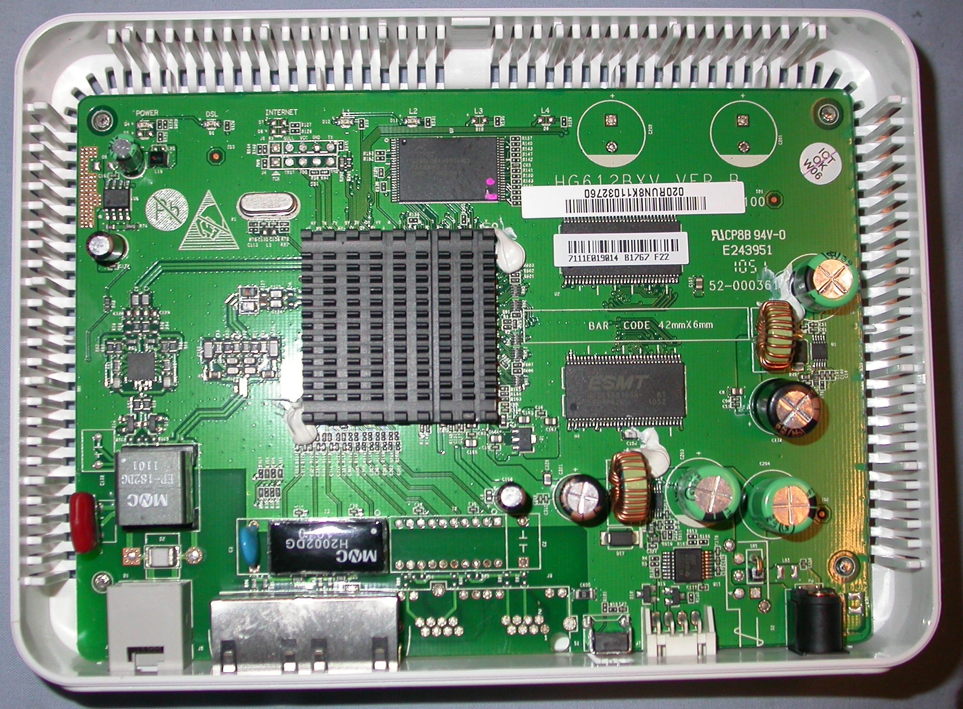
Can someone kindly tell me how to short out the reset button. here is the board...

http://www.petespcs.co.uk/wp-content/uploads/2011/06/DSCN3332-e1309417665593.jpg

(Last edited by ninjaef on 13 Feb 2018, 08:28)

At the bottom of the picture, from left to right I can guess: a telephone port, two ethernet ports, a button, a serial or JTAG connector, and a power connector. Is that button the reset button? Because it seems to have just two pins soldered to the board, and looks like shorting those tow pins would reset the device.

I just checked. Correct!
I thought that but then wondered....
The black button is encased in the metal box. The metal box is soldered to the board. So the button, in th context of those two pins soldered to the board, is already shorted. Because it is a metal box holding the button.
So it cannot be those two pins that need shorting ??

(Last edited by ninjaef on 8 Feb 2018, 16:20)

Take the board out and look at the bottom.  There are four pins on a switch like that one.  The two big "pins" on the metal cage around the switch are just mechanical supports.  The two active pins from the switch are smaller, they come out of the plastic part of the switch and go straight down through the board.  You can jump across them at the bottom.  You can also see where they come through the top of the plastic.

Almost always one switch pin is grounded and the other one goes to the CPU.  So you can use any ground point to jump the switch.

Done!

Many thanks pal.

mk24 wrote:

Take the board out and look at the bottom.  There are four pins on a switch like that one.  The two big "pins" on the metal cage around the switch are just mechanical supports.  The two active pins from the switch are smaller, they come out of the plastic part of the switch and go straight down through the board.  You can jump across them at the bottom.  You can also see where they come through the top of the plastic.

Almost always one switch pin is grounded and the other one goes to the CPU.  So you can use any ground point to jump the switch.

The discussion might have continued from here.