OpenWrt Forum Archive

Topic: MMC/SD Card module not working after upgrade to RC5

The content of this topic has been archived between 5 Mar 2018 and 2 Apr 2018. There are no obvious gaps in this topic, but there may still be some posts missing at the end.

Hey everybody,

I recently upgraded to RC5 (from RC2) and now my mmc.o module fails on load with the following:

mmc Hardware init
mmc Card init
mmc Card init
mmc: error in mmc_card_init (1)
mmc: error in mmc_init (-1)

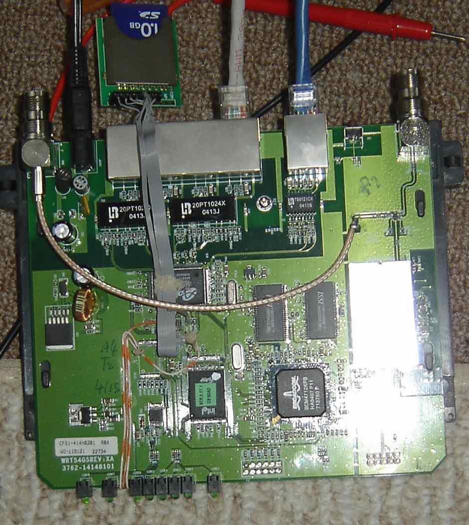
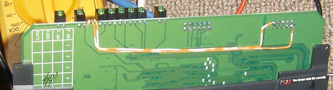
I've checked and rechecked my connections, and all appears to be fine with them.  The only change that I'm aware of making is the upgrade to RC5.  I've recompiled the driver with the same result.  I've tried the minimum stock RC5 firmware and a custom-built one.

Are there any new things added to RC5 that would interfere with the mmc module?  Have the GPIO pins been reassigned somehow?

I greatly appreciate any help that can be provided on this.  I had been using the MMC module for running a number of apps that I just won't be able to do without it.

Thanks again,
Jon

What's your exact hardware revision?

I've got a WRT54GS v1.0 (S/N CGN1) with this same problem. I found that gpio4 is stuck high when running rc5.
I upgraded from the pre-whiterussian "experimental" where gpio4 and mmc.o worked on this hardware.

I built a rc5 image without switch-core.o/switch-adm.o modules and I get the same problem, gpio 4 stuck high/mmc.o broke

In my case gpio4 is the middle wire(CLK) in the RP3 picture for the SD mod... or at least it is on the old firmware. (I had to swap SD_CLK and SD_DO defines in mmc.c)
On rc5 i tried  all gpio's and none toggled the voltage.

i just tried:

RC2... works
RC3... works
RC4... works

so that narrows it down some.

Hmmm. Isn't GPIO4 the return line *from* the MMC?
I've got a Gv2.2, with the standard mod (picture taken from http://metaligy.com/temp/wrt54g_v2.2_mmc.jpg), and it works fine even with RC5.
The GS1.0 is supposed to be similar to the Gv2.0 (the one the original mod has been designed for)...
Which module (mmc.o) are you using? Mine shows
# md5sum mmc.o
2b28f3f6c6762ef87c9cce9255ad4b7b  mmc.o
(got it from http://www.linuxdingsda.de/mmc.o)

I rolled back diag_led.c from rc5 to the rc4 version and eventually managed to get make to build a new diag.o and put it in the trx file.
Flashed that and mmc.o still doesn't work.

I built the mmc.o myself wayback during pre whiterussion days and had to swap SD_CLK and SD_DO defines. I had wired it up as per the original mod authors description but found that gpio 3 and 4 were swapped on my hardware. My hardware matches the further unverified evidence note mentioned on the wiki page which seems to make it a slightly different version than standard v1.0GS or v2.0G.

what does your unit say when you run

root@tprobe2:/# strings /dev/mtdblock/0 | grep ^gpio
gpio2=adm_eecs
gpio3=adm_eesk
gpio5=adm_eedi
gpio6=adm_rc
gpioXXXXXXXX
gpio%d

I tried the mmc.o you linked to just for kicks and it doens't work either


greg

success!
Taking mbm's suggestion that mmc.o was not setting gpiocontrol... by setting the gpiocontrol register in mmc.c I can make mmc.o work on my hardware with rc5.

By luck, the gpiocontrol register was in proper state for mmc.o to work with my hardware on previous openwrt releases. As of rc5, for my particular hardware version, my luck ran out.

The rc5 diag.o detects my hardware as a linksys v2, and sets up a "cisco button" on gpio #4. I'm guessing that sb_gpiocontrol turns on/off pull up logic for whatever gpio's you specify, which explains why my meter shows gpio#4 "stuck high"

The "cisco button setup" is what I thought I had rolled back out of diag.o in a previous posting above. I hosed that attempt up, and the changed diag.o didnt' get into .trx image.... (well eventually it did after some useless fumbling around with othe rc4/rc5 changes and when it did, mmc.o worked when I wasn't expecting it to )


Just for the record, my hardware:

gpio 3 and gpio4 are swapped from what is describe by original mmc/sd mod drawings and pictures
has no button, no silkscreened place for a button, and no flexible cisco logo for a button.
says wrt54gs on front, S/N: CGN1xxxxxxxx , FCCID: Q87-WRT54GV2

root@(none):/proc# strings /dev/mtdblock/0 | grep ^board
boardtype=0x0101
boardnum=42
boardrev=0x10
boardflags=0x0388
boardflags2=0

root@(none):/proc# nvram get pmon_ver
CFE 2004.1.30.0

this is what is I added to make my hardware work with SD Mod in rc5:

--- mmc.c       2006-06-07 01:09:56.000000000 -0700
+++ mmc.c.mine  2006-06-07 01:12:46.000000000 -0700
@@ -496,9 +496,15 @@
 static int mmc_hardware_init(void)
 {
   unsigned char gpio_outen;
+  unsigned char gpio_control;

   // Set inputs/outputs here
   printk("mmc Hardware init\n");
+  gpio_control = *gpioaddr_control;
+
+  gpio_control = (gpio_control & ~(SD_DI | SD_CLK | SD_CS | SD_DO));
+  *gpioaddr_control = gpio_control;
+
   gpio_outen = *gpioaddr_enable;

   gpio_outen = (gpio_outen | SD_DI | SD_CLK | SD_CS) & ~SD_DO;

(Last edited by framer99 on 8 Jun 2006, 16:58)

I've got a WRT54G v3 with the same problem, GPIO4 stuck high with RC5. 

Is there a compiled version of mmc available with the fix?

That seems to be suitable for me either: could u plz post the binary mmc.o?

thanks
AxeL

framer99 wrote:

this is what is I added to make my hardware work with SD Mod in rc5:

--- mmc.c       2006-06-07 01:09:56.000000000 -0700
+++ mmc.c.mine  2006-06-07 01:12:46.000000000 -0700
@@ -496,9 +496,15 @@
 static int mmc_hardware_init(void)
 {
   unsigned char gpio_outen;
+  unsigned char gpio_control;

   // Set inputs/outputs here
   printk("mmc Hardware init\n");
+  gpio_control = *gpioaddr_control;
+
+  gpio_control = (gpio_control & ~(SD_DI | SD_CLK | SD_CS | SD_DO));
+  *gpioaddr_control = gpio_control;
+
   gpio_outen = *gpioaddr_enable;

   gpio_outen = (gpio_outen | SD_DI | SD_CLK | SD_CS) & ~SD_DO;
axel__17 wrote:

That seems to be suitable for me either: could u plz post the binary mmc.o?

thanks
AxeL

You can get compiled mmc.o that works with RC5 on wrt54g v2.2 here.

Ops ... I forgot to mention I need mmc.o for WRT54G v4 (i'm using GPIO 2,3,4,7).

thnx

the #defines for your GPIO to SD_CLOCK/SD_DO etc. mappings are needed to build mmc.o, which or course depends on the version of hardware and how you wired it. For example my SD_DO and SD_CLK are defines are swapped in my mmc.c for my wrt54gs(from the original mmc.c source) because i wired to the pins as per the pictures for the original mod, but internally my hardware has the GPIOs swapped.

I was thinking it should be possible to change mmc.c so that it let's you pass GPIO->SD_XX mappings in as insmod options and then one mmc.o could be adjusted at load time to work for more than one hardware version, but i never got anything written for that.

framer99 wrote:

I was thinking it should be possible to change mmc.c so that it let's you pass GPIO->SD_XX mappings in as insmod options and then one mmc.o could be adjusted at load time to work for more than one hardware version, but i never got anything written for that.

That's a good idea smile
I can modify the mmc.c in order to cope with that, but is there anyone willing to build the module???

Ciao
AxeL

I should be able to build it if you post/email your #defines or a patch for mmc.c to take load time options.

framer99 wrote:

I should be able to build it if you post/email your #defines or a patch for mmc.c to take load time options.

Hi,

I sent you a email with details of my wrt54gs v1 (which has the same board info and FCC id) where the GPIO3 and GPIO4 are switched.
Could you please provide me the mmc.o you are using?

Thanks
-B

I must have missed the email, could you resend it please?

Let me first post the detail here so everyone could see.
Same configs as you mentioned:

WRT54GS on front,
Bottom center S/N: CGN1xxxxxxxx,
Bottom left FCCID: Q87-WRT54GV2, IC: 3839A-WRT54GV2
On the board it says WRT54GSREV:XA

I'm running RC5
Linux version 2.4.30 (nbd@ux-2y02) (gcc version 3.4.4 (OpenWrt-1.0)) #1 Sun Mar 26 19:02:04 CEST 2006
root@OpenWrt:~# strings /dev/mtdblock/0 | grep ^board
boardtype=0x0101
boardnum=42
boardrev=0x10
boardflags=0x0388
boardflags2=0
boardtype
boardflags
boardflags2=0
boardrev=%d
boardflags=%d
boardnum
boardflags
root@OpenWrt:~# nvram get pmon_ver
CFE 2004.1.30.0

(I'll update the post with links to picture)
when use GPIO util to 'poll' and short GND with 7,5,4,3 the state changes and comes back 01 00 01 so even though GPIO4 doesn't show fluctuation while running the enable;sleep;disable cycle. I think it might be Ok (I don't know any suggestions?)

I tried 2-3 versions of mmc.o which I found all around none worked (but all of those were  <13000B). I installed Deb 3.1 Sarge on VMware (as I don't have another m/c) compiled one myself with defines modified which didn't work either sad (the size was a >13000B somehow).

On Card side I have a 16MB Nokia MMC card and a 1GB SanDisk (I formatted both with Panasonic SD Formatter util after I read a thread in DD-WRT forum) no luck

What I didn't understand in the above posts that for this ver. 1 of wrt54gs did you update the diag module as well? if yes would it be possible for you to post/mail binaries of both diag and mmc modules?

Thank you
-B

My computer with buildroot on it is packed due to a recent move. I'll get it setup tonight maybe and find the mmc.o and get it posted.

From the details you posted, I believe we have the same board. My mmc.o should work for you if you physically wired it like the original kiel website pictures show. That's what i did and then altered the defines in mmc.c.  That is the original "wiring vs gpio mapping" issue for what i guess could be called v1.1 GS units.

The next issue cropped up with RC5 in that the GPIO4 was not being set as a input or output properly by the mmc.o module. mmc.o just starts using GPIO4 as an ouput, but the pull up resistor is still switched in so it seems stuck high (as i recall). The gpio_control register seems to control the pullup resistors on each GPIO. The fix was to have mmc.o write to gpio_control to make GPIO4 an ouptut. This gets you back to where things work but our particular board is wired backwards from the kiel website pics. So you still need the original swapped defines as i found previously.

I believe the diag module in rc5 sets up gpio 4 as the cisco button.. an input, pulled high by pull up resistors, so when mmc.o uses it, it needs to remove the pullup so that it can work properly as an output.

I didn't do anything with diag module in the end. Although i think if you prevent it from configuring GPIO 4 "cisco button" as an input things may work, since the GPIO4 seems to be in output after power on. But that's not the way I think it should be done. I think mmc.o should setup the GPIO's the way it wants them (as mbm pointed out way back when).

At least the above is how I remember things.

I'll get that module posted somewhere tonight hopefully.

greg

Thanks Greg,

meanwhile here are the pictures of my openwrt and the cards I tried to use, just in case if you can recall whether looks identical to your board as well

http://arghya.com/img/openwrt/board.jpg
http://arghya.com/img/openwrt/board2.jpg
http://arghya.com/img/openwrt/wrt54gsfront.jpg

I'll post my results once I get the module. My wiring is exactly as same as Kiel originally posted. The only diff would be that I'm using the SD/MMC breakout board which shouldn't matter. (the reason you see extra wires in the ribbon is because a ground appears alternatively)

framer99 wrote:

I didn't do anything with diag module in the end. Although i think if you prevent it from configuring GPIO 4 "cisco button" as an input things may work, since the GPIO4 seems to be in output after power on. But that's not the way I think it should be done. I think mmc.o should setup the GPIO's the way it wants them (as mbm pointed out way back when).

I can check back on that smile

Thanks again,
-B

(Last edited by bhaskar on 28 Sep 2006, 20:32)

This should work for the board(and wiring map) we've been discussing:
mmcgsv1XAboard.o

If not, I can unpack my actual WRT and take the module off there, I know it's working.

Let me try it and post my result, I'll also try to arrange for a mid size SD card (other than SanDisk) too, because I read somwhere >512MB and SanDisk has some issues !?:rolleyes:?!

still didn't work sad

tried couple of times to remove and insert the module
everytime I see the same thing

mmc Hardware init
mmc Card init
mmc Card init
mmc: error in mmc_card_init (1)
mmc: error in mmc_init (-1)

also tried with a Canon 32 MB card, same result everytime.. I beleive its the same module you have on your wrt but still when you get a chance if  you could please post the module you have working on your wrt?

meanwhile I will also try to get a RiDATA card.. could you pls tell me which card type/size you are using?

Thanks
-B

(Last edited by bhaskar on 30 Sep 2006, 09:23)

Hi
I Somehow have  a problem similiar to your
didnt know why but first time i solder wires i get my oem 256mb card working in WRT54GL v1 ( wich uses gpio 2 instead of 5 ) with dd-wrt 23 sp2
i made it work without modifying drivers only activating Sd/mmc in webif with the intructions for WRT54G v4
http://support.warwick.net/~ryan/wrt54g … _done.html

after that i made a clean jffs2 (in webif) and one of the wires desoldered.
I discovered that one gnd contact was not so well because i am not an expert at soldering and sort of burn it with too   much heat
after that i soldered the 2 gnd wires to same point at vss1
is this not good. the must be at diferent points?

after that i would like to know if somebody can confirm this symptoms
if sd card pluged
yellow light alway on (cant turn off)
white led off (but can be turned on by button)
DMZ led off

Mesured in card:
DI, VDD and Do have 3.3v
CS and CLK have 0.1v

is this right?

other symptoms
with dd-wrt native mmc driver if i rmmod and after load the mmc driver manualy i get with dmesg:

<0>mmc: Device does not use old GPIO layout, trying to use new GPIO layout
<0>mmc: This board has no MMC mod installed!
<0>mmc: error in mmc_init (-1)

if i use "~ # gpio disable 7" the DMZ led turns on and when i do insmod mmc i get this different error

<4>mmc: can't get major 121

can you help me please here as i am a bit confused
regards

p.s. sorry for the bad english

Other symptoms
using this comand to try to verify gpio's

while true; do gpio enable 3; sleep 1; gpio disable 3; sleep 1; done

DO (gpio 4 - Cisco buton as told but i cant confirm) always 3.3v. (????) it should variate right ?????

DI (gpio2 - white led)  variations between 0.2 and 3.3v. led fashes
CLK (gpio 3 - amber led) variations between 0.2 and a.8v but led always on
CS  (gpio 7 - dmz led) variations between 0.2 and 3.3v. led fashes
VDD off course 3.3v stable

(Last edited by mocho on 4 Oct 2006, 20:29)