hoatienii wrote:
Only triggerhappy package for support keyboard?
The content of this topic has been archived between 17 Apr 2018 and 5 May 2018. There are no obvious gaps in this topic, but there may still be some posts missing at the end.
Only triggerhappy package for support keyboard?
hoatienii wrote:Only triggerhappy package for support keyboard?
thanks! ![]()
I've just tested another interesting feature: "Commands sent from phone" ![]()
I've installed Asterisk 1.8 on my router board and tested the "System" function of Asterisk that enables it to run system commands directly from a dialplan, it works great on OpenWRT!
The idea is to create an IVR that answers the Voip call, than asks the caller to dial the login password and if the password is correct asks the caller to choose an option from a list, example:
"Welcome to the home automation server, please enter your password followed by the # key"
"Thank you"
"Press 1 to activate channel 1"
"Press 2 to deactivate channel 1"
"Press 3 to activate channel 2"
...
I don't have enough time at the moment to fully develop this feature, but if anyone is willing to help ... ![]()
(Last edited by pilovis on 30 Dec 2014, 12:15)
i have bug, i have to restart triggerhappy after type 2 button.
i have bug, i have to restart triggerhappy after type 2 button.
Is your triggerhappy configuration file correct?

Vodafone Station (a.k.a. Huawei EchoLife HG553) Home Automation Server.
The led channel status indicator on the V.S. (CH1-3) is pink (red+blue) for "Off" state and red for "On" state.
The other router on the left (vertical) is a Pirelli Voipgate ADSL router, hacked with Eutelia firmware to use it as a Voip FXS gateway (2 analog phone RJ11 ports) connected to the Vodafone Station (Asterisk 1.8 also installed on V.S.)
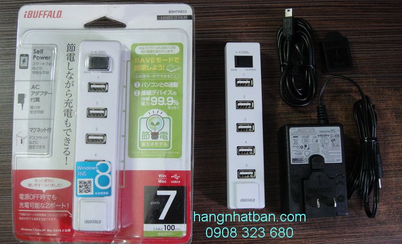
The small router with the keypad and multi-led lighted USB Hub ![]() that you see on the upper right side is another project of mine:
that you see on the upper right side is another project of mine:
Openwrt MP3 Player and Internet Radio wi-fi stereo ![]()
All components I used are TRASHWARE that means zero cost! ![]()
![]()
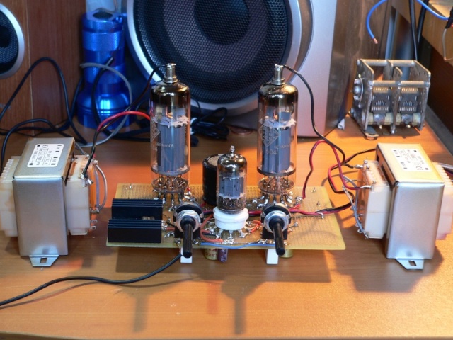
Another particularity of my OpenWRT projects:
to amplify the audio output I designed a trashware Hi-Fi stereo vacuum tube amplifier using old television's used tubes ![]()
(Last edited by pilovis on 30 Dec 2014, 20:08)
I wish i have many devices as you have ![]()
My config file
# This is an example configuration for the triggerhappy daemon (thd)
# please note that every file to be processed must end in ".conf"
#
# To view a list of supported event codes, use "thd --listevents" or
# "thd --dump /dev/input/event*"
#
# Format:
# <eventcode> <value> <command>
#
# values for key events are 1 (pressed), 0 (released) or 2 (held)
#
## control an mpd instance
# KEY_NEXTSONG          1       /usr/bin/mpc next
# KEY_PREVSONG          1       /usr/bin/mpc prev
KEY_KP1 /bin/sh /www/on_one.sh
KEY_KP2 /bin/sh /www/off_one.sh
KEY_KP3 /bin/sh /www/on_two.sh
KEY_KP4 /bin/sh /www/off_two.sh
KEY_KP5 /bin/sh /www/on_three.sh
KEY_KP6 /bin/sh /www/off_three.sh
KEY_KP7 /bin/sh /www/on_four.sh
KEY_KP8 /bin/sh /www/off_four.shTry
KEY_KP1 1 /bin/sh /www/on_one.sh &
KEY_KP2 1 /bin/sh /www/off_one.sh &
KEY_KP3 1 /bin/sh /www/on_two.sh &
KEY_KP4 1 /bin/sh /www/off_two.sh &
KEY_KP5 1 /bin/sh /www/on_three.sh &
KEY_KP6 1 /bin/sh /www/off_three.sh &
KEY_KP7 1 /bin/sh /www/on_four.sh &
KEY_KP8 1 /bin/sh /www/off_four.sh &
(Last edited by pilovis on 31 Dec 2014, 10:53)
In addition to the USB keyboard, I added a three channels digital input (on/off) just by using an old USB mouse ![]()
In any mouse there are three button switches (SW1-2-3 in the picture) that triggerhappy can handle.

Triggerhappy discovering function:
root@OpenWrt:~# thd --dump /dev/input/event*
EV_KEY BTN_LEFT 1 /dev/input/event0
# BTN_LEFT 1 command
EV_KEY BTN_LEFT 0 /dev/input/event0
# BTN_LEFT 0 command
EV_KEY BTN_MIDDLE 1 /dev/input/event0
# BTN_MIDDLE 1 command
EV_KEY BTN_MIDDLE 0 /dev/input/event0
# BTN_MIDDLE 0 command
EV_KEY BTN_RIGHT 1 /dev/input/event0
# BTN_RIGHT 1 command
EV_KEY BTN_RIGHT 0 /dev/input/event0
# BTN_RIGHT 0 command
# values for key events are 1 (pressed), 0 (released)
than to associate a command to each button when is pressed, add the following lines to your triggerhappy configuration file (/etc/triggerhappy/triggers.d/example.conf):
BTN_LEFT 1 /path/command &
BTN_MIDDLE 1 /path/command &
BTN_RIGHT 1 /path/command &
or to associate a command when the button is released:
BTN_LEFT 0 /path/command &
...
This is a generic schematic of a USB mouse:

Each button switch needs to be grounded to give "1" level for tryggerhappy, you can connect in parallel to the switch a transistor/mosfet, a relay or an optocoupler to perform this function.
P.S.: Triggerhappy does not handle the rotary encoder of the mouse, but Openwrt does, if you want to see what openwrt sees when the rotary encoder of the mouse is turned use this command:
cat /dev/input/event0 |hexdump
You'll get something like this:
Clockwise rotation:
root@OpenWrt:~# cat /dev/input/event0 |hexdump
0000000 54a4 185d 0007 1259 0002 0008 0000 0001
0000010 54a4 185d 0007 1267 0000 0000 0000 0000
0000020 54a4 185e 0000 3c9c 0002 0008 0000 0001
0000030 54a4 185e 0000 3caa 0000 0000 0000 0000
0000040 54a4 185e 0006 95d2 0002 0008 0000 0001
0000050 54a4 185e 0006 95e0 0000 0000 0000 0000
0000060 54a4 185e 0007 eda1 0002 0008 0000 0001
0000070 54a4 185e 0007 edae 0000 0000 0000 0000
0000080 54a4 185e 0008 a911 0002 0008 0000 0001
0000090 54a4 185e 0008 a91e 0000 0000 0000 0000
00000a0 54a4 185e 000a 00f2 0002 0008 0000 0001
00000b0 54a4 185e 000a 0100 0000 0000 0000 0000
00000c0 54a4 185e 000b b674 0002 0008 0000 0001
00000d0 54a4 185e 000b b680 0000 0000 0000 0000
Counter clockwise rotation:
root@OpenWrt:~# cat /dev/input/event0 |hexdump
0000000 54a4 1865 000b d96a 0002 0008 ffff ffff
0000010 54a4 1865 000b d977 0000 0000 0000 0000
0000020 54a4 1865 000e 4a6c 0002 0008 ffff ffff
0000030 54a4 1865 000e 4a78 0000 0000 0000 0000
0000040 54a4 1866 0000 9e86 0002 0008 ffff ffff
0000050 54a4 1866 0000 9e95 0000 0000 0000 0000
0000060 54a4 1866 0001 f647 0002 0008 ffff ffff
0000070 54a4 1866 0001 f654 0000 0000 0000 0000
0000080 54a4 1866 0003 cb1d 0002 0008 ffff ffff
0000090 54a4 1866 0003 cb2b 0000 0000 0000 0000
00000a0 54a4 1866 0005 a001 0002 0008 ffff ffff
00000b0 54a4 1866 0005 a00f 0000 0000 0000 0000
00000c0 54a4 1866 0007 f1c9 0002 0008 ffff ffff
00000d0 54a4 1866 0007 f1d5 0000 0000 0000 0000
00000e0 54a4 1866 000a dfe4 0002 0008 ffff ffff
00000f0 54a4 1866 000a dff2 0000 0000 0000 0000
(Last edited by pilovis on 1 Jan 2015, 13:17)
thank you your help!
(Last edited by hoatienii on 31 Dec 2014, 16:56)
After a bad new years eve ![]() I added an hand made USB PIR motion sensor
I added an hand made USB PIR motion sensor ![]()
I modified a Home PIR Motion sensor and connected the output to one button switch of the Mouse PCB you see above ![]()
The modification consists in completely disconnecting all the relay outputs from the PIR circuit and connect the two pins (N.O. output) to the mouse PCB in parallel to a switch button:

When a motion is detected this is the triggerhappy output:
EV_KEY BTN_LEFT 1 /dev/input/event2
# BTN_LEFT 1 command
when released:
EV_KEY BTN_LEFT 0 /dev/input/event2
# BTN_LEFT 0 command


The PIR motion sensor I used has also the light sensor and a timer integrated.
(Last edited by pilovis on 1 Jan 2015, 18:04)
You have many good idea ![]() . Thanks your sharing!
. Thanks your sharing!
Try
KEY_KP1 1 /bin/sh /www/on_one.sh &
KEY_KP2 1 /bin/sh /www/off_one.sh &
KEY_KP3 1 /bin/sh /www/on_two.sh &
KEY_KP4 1 /bin/sh /www/off_two.sh &
KEY_KP5 1 /bin/sh /www/on_three.sh &
KEY_KP6 1 /bin/sh /www/off_three.sh &
KEY_KP7 1 /bin/sh /www/on_four.sh &
KEY_KP8 1 /bin/sh /www/off_four.sh &
I think i have problem with usb hub, when i press keyboard 4th or 5th router can not read input from webcam and keyboard. Webcam is input event0, keyboard input event1. I will try on Barrier Breaker.
I think i have problem with usb hub, when i press keyboard 4th or 5th router can not read input from webcam and keyboard. Webcam is input event0, keyboard input event1. I will try on Barrier Breaker.
Is your USB Hub powered?
I mean, does it have his own power supply?
If not, maybe your webcam asks too much current to the router
(Last edited by pilovis on 1 Jan 2015, 19:34)
My USB hub have 4A power adapter
I've connected the 5V relays board to the router ![]()
Note: the signal to drive the relay (+3.3V) was taken from blue led's cathode (upper terminal, opposite to "+" label on PCB), the blue led is the one on the right of the group of two leds.

The relays board was luckily found rummaging through old hardware, I noticed an usb voip phone skype adapter I wasn't ever been able to use with linux, the adapter had three mini relays so I immediately destroyed it to recover the PCB portion with relays and their drivers ![]()
I took +5V to power the relays board from the lower USB connector but noticed that the router may have some problem when other devices are connected to this port due to increased load current, but if you do not connect anything else to this USB port it is OK.
As soon as I can I will add a +5V voltage regulator and will connect it directly to the + 12V router's power supply.
(Last edited by pilovis on 3 Jan 2015, 09:48)
You should use hot glue to hold wire on pcb ![]()

The obvious answer to the power situation is to use 12 volt relays. Or put a properly sized resistor in series from the 12v bus to each 5 volt relay coil, though that wastes energy.
You could clean up the motion detector considerably by bypassing its power system and relay and just using a 5 volt interface to the USB mouse board. The transistor that drives the relay now could pull one of the button lines to ground.
You could clean up the motion detector considerably by bypassing its power system and relay and just using a 5 volt interface to the USB mouse board. The transistor that drives the relay now could pull one of the button lines to ground.
Good suggestion! ![]()
Thanks.
About the 12V relay you're right but I want to use recovered components from my trashware's drawer as much as possible.
The drop resistor solution is not suitable, the current consumption span of the relay board is too big from "on" to "off" state, during "off" state you may have too much voltage on the board (startup relay coil transient voltage too big).
The best solution would be having a switching voltage regulator to reduce waste of energy.
(Last edited by pilovis on 3 Jan 2015, 09:07)
Separate resistor for each relay, so that turning one on doesn't affect the voltage to the others.
There is a nice 12v to 5v switching regulator board easy to repurpose from any phone charger that plugs into a car.
I have old CRT monitor. Could use it for amplifier? ![]()
(Last edited by hoatienii on 4 Jan 2015, 02:39)
I have old CRT monitor. Could use this for amplifier?
I designed a special one to sonorize my OpenWrt Wi-Fi Internet radio.
This is my Openwrt Internet Hi-Fi stereo "tube" radio, I think it is the only OpenWRT vacuum tube project in the world ![]()
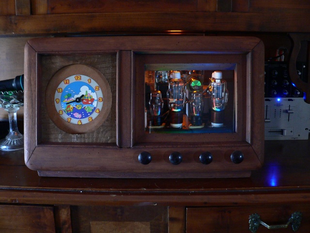

note: all tubes I used were never used before (New Old Stock) and were made in 1944 by RCA for Army & Navy, except for "magic eye" that was built in 1951 in Germany.
(Last edited by pilovis on 4 Jan 2015, 02:28)
Finally, the 12V to 5V switching voltage regulator was added ![]()
I recovered it from a cheap car USB charger.
Anyway, the Vodafone station still have USB problems, the USB support for this router is broken!
This the final version of my Home Automation Router, wires have been glued to PCB and the two boards are kept in place with double-sided adhesive tape:

(Last edited by pilovis on 5 Jan 2015, 00:11)
Finally, the 12V to 5V switching voltage regulator was added
I recovered it from a cheap car USB charger.Anyway, the Vodafone station still have USB problems, the USB support for this router is broken!
This the final version of my Home Automation Router, wires have been glued to PCB and the two boards are kept in place with double-sided adhesive tape:
like!
i have error when connet keyboard and webcam to hub.
[    8.680000] usb 1-1: new full-speed USB device number 2 using ohci-platform
[    8.900000] hub 1-1:1.0: USB hub found
[    8.900000] hub 1-1:1.0: 4 ports detected
[    9.210000] usb 1-1.1: new low-speed USB device number 3 using ohci-platform
[    9.300000] usb 1-1.1: device descriptor read/64, error -62
[    9.490000] usb 1-1.1: device descriptor read/64, error -62
[    9.680000] usb 1-1.1: new low-speed USB device number 4 using ohci-platform
[    9.770000] usb 1-1.1: device descriptor read/64, error -62
[    9.960000] usb 1-1.1: device descriptor read/64, error -62
[   10.150000] usb 1-1.1: new low-speed USB device number 5 using ohci-platform
[   10.570000] usb 1-1.1: device not accepting address 5, error -62
[   10.650000] usb 1-1.1: new low-speed USB device number 6 using ohci-platform
[   11.070000] usb 1-1.1: device not accepting address 6, error -62
[   11.070000] hub 1-1:1.0: unable to enumerate USB device on port 1
[   11.170000] usb 1-1.4: new full-speed USB device number 7 using ohci-platform
[   11.260000] usb 1-1.4: device descriptor read/64, error -62
[   11.450000] usb 1-1.4: device descriptor read/64, error -62
[   11.640000] usb 1-1.4: new full-speed USB device number 8 using ohci-platform
[   11.730000] usb 1-1.4: device descriptor read/64, error -62
[   11.890000] eth0: link up (1000Mbps/Full duplex)
[   11.920000] usb 1-1.4: device descriptor read/64, error -62
[   12.110000] usb 1-1.4: new full-speed USB device number 9 using ohci-platform
[   12.530000] usb 1-1.4: device not accepting address 9, error -62
[   12.610000] usb 1-1.4: new full-speed USB device number 10 using ohci-platfor                                                                                        m
[   13.100000] usb 1-1.4: device not accepting address 10, error -62
[   13.210000] hub 1-1:1.0: unable to enumerate USB device on port 4